Firmware
Introduction
The LPA firmware is an embedded program written in C for the ATmega328 microcontroller. It performs the following main functions:
- Reads an LPF file from an SD card, connected to the microcontroller via a Serial Peripheral Interface (SPI).
- Reads light intensity (“grayscale”) values from the LPF file.
- Updates the intensity of a set of LEDs under control of TLC5941 drivers, by transferring the appropriate grayscale values via SPI.
The firmware has been divided in different modules that perform separate functions. All the relevant variables inside a module are named as <module_name>_<variable_name>. Functions are named in a similar format. Modules are written such that, when possible, the assignment of hardware resources is defined by a “configuration” step, controlled by a separate config.h file that is included during compilation. This facilitates porting the individual modules to different projects, or transferring this project to a similar microcontroller.
In this section, we will describe the high-level behavior of the firmware main program, the contents of each module, and the config.h file.
States of the Firmware Program
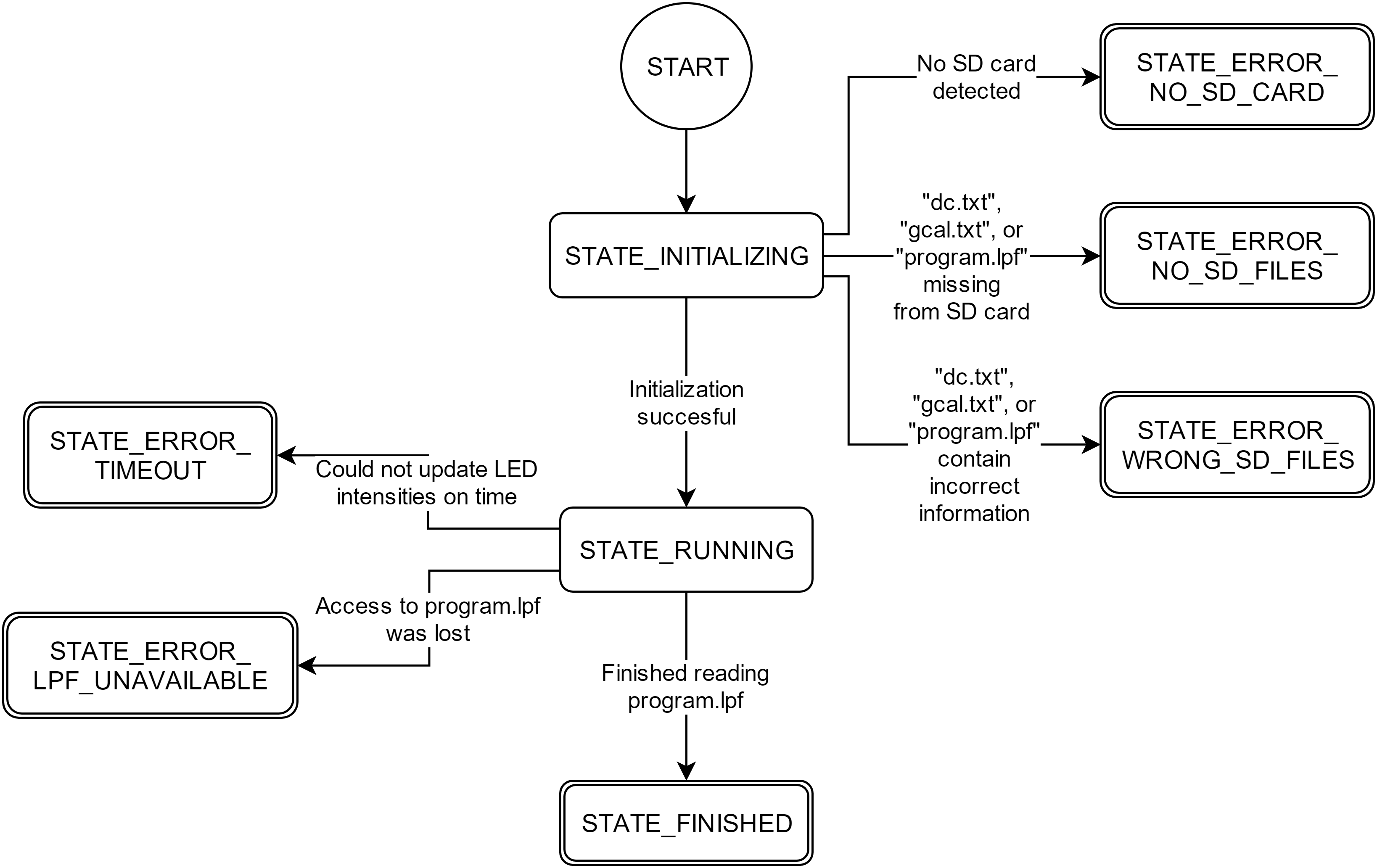
In this diagram, rounded squares denote states, rounded squares with double edges denote terminal states, and arrows denote transitions. The circle labeled as START denotes the state of the program upon booting.
The LPA will often need to respond differently to the same stimuli, especially under error conditions. This is best managed by modeling the system as a finite state machine, in which the device’s behavior is a function of both the inputs and the current state. In the firmware, the current state is contained in a single variable. Supplementary Table S4 enumerates the different states of the device, and Supplementary Fig. S14 shows the transition diagram between different states. Each pattern displayed by the status LEDs corresponds directly to each state (Supplementary Tables S3 and S4).
TLC5941 Driver module
The TLC5941 driver module is available as a separate project (https://github.com/castillohair/Tlc5941_library). This module is heavily based on the “Demystifying the TLC5940” book10, with a few additions to make the library work with the TL5941 instead of the TL5940, the Atmega328 USART module instead of the SPI module, among others. In short, this module incorporates functions to:
- Initialize the TLC5941
- Set grayscale values, one at a time or all at once.
- Change dot correction values, one at a time or all at once.
In addition, several precompiler flags are available to define the pins used to interact with the TLC5941. These can be changed inside “config.h” file without modifying the library’s source code.
MsTimer Module
The MsTimer (millisecond timer) module incorporates functions to define a timer that calls a set of functions (“callbacks”) periodically, with a period specified in milliseconds. This module uses the Atmega’s Timer1 to generate interrupts via compare events. The module incorporates functions to
- Initialize the relevant registers of Timer1.
- Add callbacks and their respective periods in milliseconds.
- Start and stop the module.
StatusLeds Module
The StatusLeds module is a simple module that abstracts the toggling of status LEDs on the board. It incorporates functions to
- Initialize the pins that control the status LEDs.
- Set the status of an LED to on or off.
- Toggle an LED to the opposite state.
SD Card Reading
SD card reading is performed using the Arduino SD card library. For details on how to set the library before compiling, refer to the Supplementary Method on firmware programming.
The config.h File
The config.h file should be included during compilation of every file associated with the project. By doing this, preprocessor directives defined in config.h (i.e. #define instructions) replace the ones defined in the modules by default. This allows us to override the default behavior of the module without changing the code, a procedure called “configuration”.
Additionally, the firmware has been made such that an arbitrary number of LEDs in any arrangement is possible. The number of LEDs is specified through the number of LED drivers (Tlc5941_N), whereas the arrangement is specified as a constant array (well2channel). The arrangement corresponding to the 24-well LPA is included by default, but a file called “config_96.h”, which illustrates the configuration for a hypothetical 96-well LPA, is also included.
firmware.cpp
This file contains the main function of the firmware (main()). Other important parts are:
- Variables dotCorrectionValues[] and grayscaleCalibration[], which store dot correction and grayscale calibration values after reading them from files dc.txt and gcal.txt in the SD card.
- Definitions of constants corresponding to the states (Supplementary Table S4, all the #define System_<state_name> instructions), a variable containing the current state (System_state), and functions to evaluate the state (System_SetState(), System_IsState() and System_IsNotState()).
- A function to update the LPA LEDs, UpdateLeds().
- A function to update the status LEDs based on the current state, UpdateStatusLeds().
In short, the main function does the following:
- Initializes the TLC5941 module.
- Initializes the MsTimer and the StatusLeds module.
- Initializes the SD card module.
- Reads and parses both dc.txt and gcal.txt files.
- Opens the “program.lpf” file.
- Reads the time step size specified in “program.lpf”, and initializes timers with MsTimer so UpdateLeds() is called with the appropriate frequency.
- Waits for UpdateLeds() to be called.
- Reads a new set of intensity values from the SD card and places them on a buffer, such that UpdateLeds() can send them to the TLC5941s when it is called again.
- Repeat from 6 until “program.lpf” file has been read completely.